3 Pin Potentiometer Wiring Diagram

2001 Hyundai Elantra Wiring Diagram, Hyundai Elantra Wiring Diagrams 1998 to 2016, 8.63 MB, 06:17, 15,957, John Amahle, 2018-11-17T16:37:24.000000Z, 19, 2001 Hyundai Elantra Radio Wiring Diagram For Your Needs, www.dentistmitcham.com, 1404 x 1200, jpeg, hyundai elantra wiring diagram radio 2001 forums needs, 20, 2001-hyundai-elantra-wiring-diagram, Anime Arts
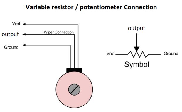
Arduino's pin a0 to a5 can work as analog input. The analog input pin converts the voltage (between 0v and vcc) into integer values (between 0 and 1023), called adc value or analog value. By connecting an output pin of the potentiometer to an analog input pin, we can read the analog value from the pin, and then converts it to a meaningful value. 3 pin potentiometer wiring diagram.
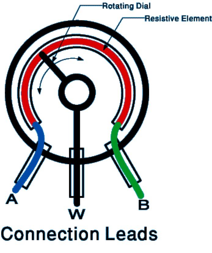
To properly read a wiring diagram, one offers to learn how the components within the method operate. For example , in case a module is usually powered up and it sends out a signal of half the voltage in addition to the technician will not know this, he'd think he has a. Preset potentiometer (trimpot) preset potentiometer pinout. A trimpot is another type of potentiometer that comes in small package. It has three leads and can be easily mounted on breadboard or perf board for quick prototyping. The value of the pot can changed by varying the knob on top of it. Potentiometer as an electronic control unit. Wiring a potentiometer is straightforward. First, you’ll need to ground the first terminal.
Pin auf 電子

potentiometer is a 3 terminal device.It is used to change the voltage from 0 to the applied

3 pin potentiometer pinout - Cerca con Google | Electronic circuit projects, Computer power

Картинки по запросу 3 pin potentiometer pinout | Circuit diagram, Math, Circuit

[Proper] Potentiometer Connection and Circuit Diagram | Circuit, Circuit diagram, Electronics
![3 Pin Potentiometer Wiring Diagram [Proper] Potentiometer Connection and Circuit Diagram | Circuit, Circuit diagram, Electronics](https://i.pinimg.com/originals/09/89/7c/09897ca1bed578ae6e0db60500902c5c.png)
3 Pin Potentiometer Wiring Diagram - Search Rasp

Potentiometer | Mbed

Wiring a Digital Potentiometer with MCP4161 | 14core.com
How to use a potentiometer with Arduino - Ardumotive Arduino Greek Playground

3 Pin Trimmer Capacitor Connection
